Nemotek's WLC Cost Analysed

...
August issue of Yole Developpement's 3D Packaging Magazine publishes reverse engineering analysis of Nemotek's wafer level camera. The VGA WLC is mostly based on Tessera technology. SystemPlus Consulting, the author of the article, concludes that the whole camera cost is 30 cents (not including image sensor), 50% of that is its wafer level package:

8:46 AM

Omnivision Forecasts Big Revenue Increase

...
Seeking Alpha: In its quarterly earnings report "OmniVision is forecasting a jaw-dropping increase in next quarter's revenue to $355 million to $390 million, far higher than the consensus $269 million estimates. The revenue forecast is 38% to 50% higher sequentially. You don't boost your sales outlook without something big in the works.

...OmniVision's bullish forecast all but confirms it will be supplying the rumored iPhone 5. The optimistic sales outlook is yet another indication that Apple will be launching the iPhone 5 very soon.
"

Seeking Alpha's transcript of Omnivision's quarterly earnings call has few interesting bits of info:

  • The cash balance went down by $94M due to the decision to increase the inventory
  • The bulk of this inventory is OmniBSI-2 devices
  • An unusually big increase in 1.3MP sensor shipments in the past quarter is explained by the adaption of HD video across all mobile devices
  • The reported GAAP gross margin is 19.1% and might go down further next quarter. This is explained by the higher cost of OmniBSI-2 sensors and their bigger proportion in overall shipments

Some quotes:

Shaw Hong, CEO:

"In Q1, we recorded revenues of $258 million and we shipped 166 million image sensors. On a non-GAAP basis, gross margin was 19.5% and net income was $11.6 million.

...Our cash balance decreased by $94 million to $237 million and our inventory balance increased by $112 million to $403 million. These were results of a strategic decision to build inventory to support our fast growing business in the face of strong seasonal demand.
"

Hasan Gadjali, VP Marketing and Business Development:

"...our most advanced OmniBSI-2 technology such as OV90772, OV5690, OV8850 and OV12830, ...are now being selected for premium mobile device."

Anson Chan - CFO & VP, Finance:

"R&D expense in the first quarter of fiscal 2013 totaled $28.8 million, a 6.2% increase from the $27.2 million in our fiscal 2012 fourth quarter. The increase in R&D expense was driven by an increase in R&D headcount.

...We currently expect our R&D expense in the second quarter of fiscal 2013 will increase further at a low double-digit percentage rate.
"
3:38 AM

Sony Announces New Imagers, ISPs

...
Sony Cx-News Vol. 69 mostly consists of image sensor announcements. The most interesting one is the high-speed 12.4MP 1/1.7-inch IMX144CQJ BSI CMOS sensor. The sensor is based on 1.85um pixels and delivers 35fps at full resolution. It also has a 4K video mode (4096H x 2160V) at 60fps.

The new sensor is said to have 1.3 times the sensitivity and 1.9 times the saturation signal level of the previous generation Sony product, IMX078CQK based on a smaller 1.55um pixel:


The angular light acceptance has also been improved over the 1.55um pixel:


Another new announcement is three HD video sensors for industrial applications, based on 2.8um and 3.75um pixels and having MIPI interface:

IMX137LQK:

  • 1/4-inch, 2.8um pixel, 1.43MP resolution
  • Frame rate: 60 fps

IMX139LQJ:

  • 1/3-inch, 3.75um pixel 1.37MP resolution
  • Frame rate: 120 fps

IMX140LQJ:

  • 1/2.8-inch, 2.8um pixel, 2.38MP resolution
  • Frame rate: 60 fps

ICX693AQA (RGB version) and ICX693AKA (CMYG version) CCDs has SVGA (800 x 600) resolution and 50fps speed in 1/3-inch format. The new CCDs have 6um pixels. Comparing to a previous generation VGA CCDs, even though their unit cell area is approximately 34% smaller, their sensitivity is 2.4 times (+7.7 dB) greater, saturation signal level is 2.6 times (+8.3 dB) better and smear characteristics are approximately -15 dB, all of which add up to a significant boost in improvement.

Other than image sensors, Sony announced a new ISP + H.264 Encoder chip series called "Xarina" and targeting next generation of IP Surveillance cameras. The CXD4135GG (chip) and CXD4235 (chip+DRAM module) support WDR imaging, motion detection, face detection, noise reduction (3D-NR/2D-NR), digital image stabilization, and other intelligent functions. H.264 and Motion JPEG video encoding support video streaming at up to 1920 x 1080p at 60 fps.

1:09 PM

JVC-Kenwood Acquires Altasens

...
It was brought to my attention that AltaSens, Inc. has announced that it has been wholly acquired by JVC KENWOOD on Aug. 10, 2012. After the acquisition Altasens becomes a wholly owned subsidiary of JVC KENWOOD.

"AltaSens’ products and technology have tremendous applicability to JVC KENWOOD’s existing products such as security camera, professional video camera, and future product developments," said Kensuke Kawai, JVC KENWOOD’s Officer and CTO. "AltaSens will be aiming to accelerate growth as a self‐standing company with numerous outside world‐class customers and tremendous sales potential in this rapidly growing industry."

Lester Kozlowski, AltaSens Founder, CTO, and COO stated, "We are extremely excited by this acquisition and the tremendous opportunity to work even more closely with JVC KENWOOD in the future. We are equally as thrilled with the renewed focus on quickly creating unique products leveraging innovative sensor technology for our existing and prospective customers.  We consequently look forward to once again providing the world’s best image sensors."

JVC Kenwood CTO Kensuke Kawai becomes Altasens' President and CEO.

The news appears to be announced only on Altasens web site. Thanks to PM for pointing me to it!

Update: I was told that AltaSens used to be a fully owned subsidiary of Olympus Corp. Now JVC-Kenwood aqcuired it from Olympus. With this AltaSens becomes a fully owned subsidiary of JVC-Kenwood.
1:55 PM

Omnivision Rumored to Invest in China 12-inch Wafer Foundry

...
Digitimes' sources report that OmniVision is looking to buy a stake in Wuhan Xinxin Semiconductor Manufacturing, a 12-inch wafer fab in China. Wuhan Xinxin is a joint venture between SMIC and the Wuhan government. SMIC managed Wuhan Xinxin for the local government until around mid-2011 when both parties entered a joint venture agreement allowing SMIC to not only manage but also invest in the 12-inch fab.

Reportedly, Omnivision has already proposed to buy the shares of the 12-inch fab held by SMIC and Wuhan City for approximately US$80M. The talks are supposed to be finalized in the middle of September.

So far OminiVision uses TSMC and Powerchip fabs for its sensors. In response to the speculations, TSMC reiterated that its cooperation with OmniVision remains unchanged.

Wuhan Xinxin now has a monthly capacity of about 20,000 12-inch wafers, with a goal of achieving a production capacity 45,000 units per month.
11:40 AM

How to Measure PTC

...
Albert Theuwissen explains how to measure and interpret the Photon Transfer Curve (PTC) in his latest blog post.
11:29 AM

Tobii Named World Economic Forum Technology Pioneer

...
Sweden-based Tobii Technology, a maker of eye tracking and gaze interaction systems, announces its selection as a Technology Pioneer by the World Economic Forum.

With Google Project Glass and Mirosoft Fortaleza Glasses the eye tracking might play a big role in the future applications.

Earlier this year Tobii was recognized by Microsoft for its development of Tobii Gaze, an eye-tracking computer interaction method for the Windows that is said to provide users a more natural, comfortable and intuitive interaction method for computers as the company continues to pursue its vision of eye tracking-enabled consumer computing.

In this Youtube video Tobii's CTO and co-founder John Elvesjö talks about the company plans to bring the eye tracking to the mass market:


Tobii's PCEye eye control device in action is shown in another Youtube video:


Google Project Glass video:


11:24 AM

Toshiba Announces Two HD Video Sensors

...
PR Newswire: Toshiba announces two new HD video sensors to its CMOS sensor lineup. The 1/7-inch T4K08 is Toshiba's first native 720p/30fps HD video sensor combining 1.75um FSI pixel with SoC image processing on the chip. The 1/4.4-inch T4K24 is Toshiba's first native 1080p/30fps FHD format 1.75um FSI pixel sensor.

The T4K08 format sensor and T4K24 image sensor samples are currently available with mass production, for both devices, targeted at fourth quarter, 2012. Sample pricing for the T4K08 720p is $3.00. The T4K24 1080p is priced at $4.00, also in sample quantities.

10:38 AM

OmniBSI+ Line Extended Down to VGA Chips

...
Omnivision launches its smallest VGA SoC for front-facing camera applications in mobile devices. The 1/13-inch OV7695 utilizes 1.75um OmniBSI+ pixel and is housed in a compact 2.4 x 2.3 mm package:
The OV7695 is currently available for sampling, and is expected to begin mass production in Q1 2013.
10:27 AM

PrimeSense named World Economic Forum 2013 Technology Pioneer

...
PR Newswire: PrimeSense is one of 23 of the world's most innovative technology start-ups that are being recognized as a World Economic Forum Technology Pioneer.

A selection committee, comprised of technology and innovation experts, academics and venture capitalists, reviews all applications before making its recommendation to the World Economic Forum.

"PrimeSense is proud to receive the World Economic Forum award and honored to be recognized as a Technology Pioneer," said PrimeSense CEO, Inon Beracha. "After taking part in revolutionizing the gaming industry and the living room TV experience, PrimeSense 3D sensing technology is now entering a variety of additional new markets, such as robotics, industrial markets, interactive displays, healthcare, retail and more. In all these markets PrimeSense technology transforms machines and devices by giving them the gift of sight, enabling them to see and interact with their environment."

A Youtube video from PrimeSense featurs president and co-founder, Aviad Maizel talking about the company's potential:

12:55 PM

S3 Group Licenses DAC to Aptina

...
Business Wire: S3 Group, a provider of IP and services, has licensed a Video DAC to Aptina for an upcoming CMOS image sensor. It's said to be a customized, very low area, single Video DAC supporting Composite Video.

"We chose S3 Group because of their expertise in DAC design, their extensive knowledge of the target process, the availability of a suitable DAC, their price competiveness and that they could meet our delivery schedule.," said Sion Quinlan, Aptina’s Director of Circuit IP.
12:38 PM

Omnivision Announces 5MP 1.4um OmniBSI+ Sensor

...
PR Newswire: OmniVision announces the 1/4-inch OV5648, a low-cost 5MP sensor for smartphones and tablets. Using the 1.4um OmniBSI+ pixel, the OV5648 is a technology upgrade of the original OmniBSI-based OV5647. The new sensor combines a smaller die size with higher quality photography and HD video. The sensor can fit into a 6 x 6 mm fixed focus module with a z-height of less than 4.5 mm:
OmniBSI+ pixel offers improvements over our original OmniBSI architecture, including a 60% increase in full-well capacity and a significant improvement in low-light performance. The 1/4-inch OV5648 is capable of capturing 720p HD video at 60 fps and 1080p HD video at 30 fps.

The OV5648 is currently sampling and is expected to enter mass production in Q1 2013.
12:08 PM

Omnivision Announces NTSC Sensor for Automotive Applications

...
PR Newswire: Omnivision announces the OV7955, a low cost NTSC-resolution image sensor for mainstream automotive applications such as rear-view, surround-view and blind spot detection systems. The output is both analog and digital - a DAC is converting its digital output back into the analog domain:


"In light of the imperatives of the Cameron Gulbransen Kids Transportation Safety Act, we anticipate heightened demand for rear-view camera systems. To address that need, we are bringing to market an image sensor that is 40 percent smaller than competing products, and that is offered at an extremely competitive cost," said Jeff Morin, automotive marketing manager at OmniVision. "We are extremely pleased with the OV7955's low cost, small footprint and exceptional performance, and have already begun shipping this sensor to major automotive manufacturers from around the world for incorporation into their mainstream automotive designs."

The new sensor is based on 6um-sized OmniPixel3-HS pixels with sensitivity of 16 V/Lux-sec, maxSNR of 38dB and dark current of 16 mV/s @ 50C. The OV7955 is housed in a compact 5.7 x 5.4 mm aCSP package.
12:55 AM

What is pilgrim nut ? and its use and purpose ?

...


ThePilgrim nut system used with the shaft and bore surfaces dry and degreased (except for cast steel propellers where wiping of the bore with an oil soaked rag is recommended) achieves the correct push up by a calculation based on the predictable friction of dry surfaces. The calculation gives the hydraulic pressure suitable for the prevailing ambient temperature lo produce the required push up. The operation is of course checked by measuring the push up and the hub movement relative to the increase of jacking pressure is monitored by a dial gauge.
The Pilgrim nut (Figure a ) employed for propeller mounting. has an internal nitrile rubber tube which when inflated hydraulically, forces a steel loading ring against the hub. Outward movement of the ring from the flush position must not exceed one third of the ring width, to avoid rupture of the rubber tube. Temperature of hub and shaft are recorded and also used to find the correct final push up pressure from the table provided in the instruction book.

The propeller, after a check with the blue marker of the mating surfaces, is positioned and initially jacked on to the shaft taper. before the Pilgrim nut is used to apply an initial loading of perhaps 67 bar pressure. A reference mark is made at this point about 25 mm from the forward end of the hub. The nut is then turned until the loading ring is again flush (venting hydraulic flutd) becore full pressure is applied. During this stage, the dial gauge should show the movement. A second mark 25 mm from the forward face of the hub is then made. Push up, registered by the distance between the two reference marks, is measured and noted.

The nut is again vented and turned to bring the loading ring to the flush position and finally nipped up with a tommy bar. The Pilgrim nut can be reversed and used with a withdrawal plate and studs (Figure b) for removal of the propeller. To safeguard against any violent movement at release, wooden blocks are inserted as shown, and a gap of only a little more than the push up distance is left.

The Pilgrim keyless system owes its name to T. W. Bunyan.


Pilgrim Nut Operation

Pilgrim nut is used to ensure a solid frictional drip between the propeller and shaft. The use of pilgrim nut facilitates the transmission of the engine torque without using the key.
Pilgrim nut is basically a hydraulic jack with threads, which is screwed into the slot provided on the tail shaft . The propeller is forced onto the tapered tail shaft region by using a steel ring, which receives the thrust from a hydraulically pressurized nitrile rubber tyre. The same process can be revered, by using an additional withdrawal plate attached to the propeller boss by studs , in order to take the propeller off off the shaft. In simple, when the tyre is pressurized the propeller will come off the tapered region.

The Pilgrim nut Assembly and Removal


Mounting and unmounting arrangements for pilgrim nut  

Assembly


Propeller bedded to tailshaft and jacked up to usual shop mark. The Pilgrim nut is then screwed on the shaft with the loading ring against the prop boss. With the lever operated, high pressure grease gun, grease is pumped into the inner tube inside the nut at around 600 bar, ( w.p. stamped on nut, not to be exceeded), the prop will be pushed sufficiently up the taper to give the required frictional grip. The pressure is then released and the nut is rotated until it is hard up against the aft face of the prop hub and locked, fair water cone then fitted.

Removal

After removal of fair water cone and the locking plate, the pilgrim nut is removed, reversed and together with a loose shock ring is screwed back onto the shaft. A strong back is fitted and secured with studs to the prop boss. Grease is now inserted to the system expanding the inner tube forcing the loading ring, strongback, withdrawal studs and prop aft.

Advantages

    • Precise tightening working on a measured applied load
    • Adequate interference fit
    • no heat used
    • Simple and safe to operate
    • No shock loads applied
    • Considerable saving in man power and time


Write to me at marinenotes4u@gmail.com,283928@gmail.com.::MK::.

New Scale's AF Motor Uses TDK-EPC Multi-Layer Piezoelectrics

...
New Scale Technologies patented its reduced-voltage piezoelectric AF motor and drive system, capable of operating directly from battery voltage as low as 2.3 VDC. With no need for boost circuits the system size and component cost is reduced. The low-voltage motor is said to be more than five times smaller than commercial electromagnetic linear motor systems and uses 40% less power, while delivering competitive force and range of motion.

The latest version replaces the original SQUIGGLE motor’s monolithic piezoelectric elements with advanced multi-layer piezoelectric elements from TDK-EPC to achieve the reduced operating voltage. The NSD-2101 drive circuit was developed in partnership with ams using New Scale’s control algorithms to increase motor efficiency and refine the motor control capabilities.

U.S. patent # 8,217,553 was issued July 10, 2012 to inventors Qin Xu, David Henderson and Daniele Piazza.

The reduced-voltage SQUIGGLE micro motor
and drive ASIC are displayed by Daniele Piazza,
co-inventor with Qin Xu and David Henderson of
the newly patented technology.
12:26 AM

Sony Announces "Exmor RS" Stacked Products

...
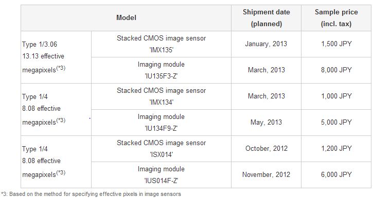
Sony announces the commercialization of "Exmor RS", the CMOS image sensor incorporating a unique, newly-developed "stacked structure". Shipments will commence in October. Sony is introducing three models of the “Exmor RS,” stacked CMOS image sensor with 1.12um pixels, for use in smartphones and tablets with three corresponding camera modules incorporating these sensors:

Above: Camera modules (left to right): the IU135F3-Z, IU134F9-Z and IUS014F-Z
Below: "Exmor RS" stacked CMOS sensors (left to right): IMX135, IMX134 and ISX014

IMX135, the 13.13MP (eff) 1/3.06-inch sensor model and IMX134, the 8.08MP (eff) 1/4-inch sensor feature "RGBW coding" and "HDR movie" function. The "RGBW coding" has W (white) pixels in addition to conventional RGB pixels, and leveraging Sony’s proprietary device technology and signal processing to improve low-light sensitivity without compromising its high resolution. "HDR movie" function enables two different exposure conditions to be configured within a single screen when shooting, and seamlessly performs appropriate image processing to generate optimal images with a wide dynamic range.

The other “Exmor RS” sensor is the ISX014, a 1/4-inch model with 8.08MP (eff), which has a built-in camera signal processing function that, apparently, does not support "RGBW coding" and HDR.

Sony will also bring to market three compact AF camera modules equipped with newly-designed lens optimized for the 1.12mm pixels: the IU135F3-Z, IU134F9-Z and IUS014F-Z. The IU135F3-Z module incorporates fast F2.2 lens. The IU134F9-Z (W:8.5 x D:8.5 x H:4.2mm, excluding FlexPCB) is thin and compact.

The release shipment schedules and prices are in the table below:


Sample image captured at 10 lux illumination


A brief stacked sensors spec comparison:


The new camera module comparison:

2:28 PM

2ps-Time Resolving Camera

...
TED published MIT Ramesh Raskar's talk about his 2ps exposing camera on Youtube:


More pictures from the 2ps camera are at MIT femtophotography.info site. Thanks to EF for the link!
2:33 PM

What is A Clamp Meter? How does A clamp meter work? How To Use a Clamp meter?

...

What is A Clamp Meter?

An electrical meter with integral AC current clamp is known as a clamp meter, clamp-on ammeter or tong tester.
In order to use a clamp meter, only one conductor is normally passed through the probe; if more than one conductor is passed through then the measurement would be the vector sum of the currents flowing in the conductors and would depend on the phase relationship of the currents. In particular if the clamp is closed around a two-conductor cable carrying power to equipment the same current flows down one conductor and up the other, with a net current of zero. Clamp meters are often sold with a device that is plugged in between the power outlet and the device to be tested. The device is essentially a short extension cord with the two conductors separated, so that the clamp can be placed around only one conductor.
The reading produced by a conductor carrying a very low current can be increased by winding the conductor around the clamp several times; the meter reading divided by the number of turns is the current, with some loss of accuracy due to inductive effects.
Clamp meters are used by electricians, sometimes with the clamp incorporated into a general purposemultimeter.
It is simple to measure very high currents (hundreds of amperes) with the appropriate current transformer. Accurate measurement of low currents (a few milliamperes) with a current transformer clamp is more difficult.
Less-expensive clamp meters use a rectifier circuit which actually reads mean current, but is calibrated to display the RMS current corresponding to the measured mean, giving a correct RMS reading only if the current is a sine wave. For other waveforms readings will be incorrect; when these simpler meters are used with non-sinusoidal loads such as the ballasts used with fluorescent lamps or high-intensity discharge lamps or most modern computer and electronic equipment, readings can be quite inaccurate. Meters which respond to true RMS rather than mean current are described as “true RMS”.
Typical hand-held Hall effect units can read currents as low as 200 mA, and units that can read down to 1 mA are available.
The Columbia tong test ammeter, manufactured by Weschler Instruments, is an example of the iron vane type, used for measuring large AC currents up to 1000 amperes. The iron jaws of the meter direct the magnetic field surrounding the conductor to an iron vane that is attached to the needle of the meter. The iron vane moves in proportion to the strength to the magnetic field and thus produces a meter indication proportional to the current. This type of ammeter can measure both AC and DC currents and provides a true RMS current measurement of non-sinusoidal or distorted AC waveforms. Interchangeable meter movements can be installed in the clamping assembly to provide various full-scale current values up to 1000 amperes. The iron vane is in a small cylinder that is inserted in a space at the hinged end of the clamp-on jaws. Several jaw sizes are available for clamping around large conductors and bus bars up to 4+1⁄2 inches (110 mm) wide
you can see parts of a clamp meter in picture below:

How does A clamp meter work?

 An amp meter or ammeter is a device that measures current in a circuit in amperes which is a measurement of the movement of electrons over a point through time.


The first ammeters were galvanometers, which exploit the deflection of a needle by a current through a coil (magnetic field), accomplished via spring action; galvanometers can measure only direct current (DC). Moving iron ammeters can measure both DC and alternating current (AC) and replace the needle with a piece of iron which is acted on by deflection across the magnetic field. To measure larger currents, a shunt (which acts as a resistor) is added to the system; most of the current is redirected through the shunt and, because the resistance across the shunt is known, it remains possible to measure the current.
A clamp-on ammeter, also known as a current clamp or current probe, can be clamped around a conductor via its two jaws, allowing the monitor to get a reading of amperage. Generally speaking, clamp-on ammeters use their jaws to detect the conductor’s magnetic field, which acts on an iron vane, or a sensitive cylinder of iron, which provides a reading of current.


Non-clamp-on ammeters
The first ammeters were galvanometers, which exploit the deflection of a needle by a current through a coil (magnetic field), accomplished via spring action; galvanometers can measure only direct current (DC). Moving iron ammeters can measure both DC and alternating current (AC) and replace the needle with a piece of iron which is acted on by deflection across the magnetic field. To measure larger currents, a shunt (which acts as a resistor) is added to the system; most of the current is redirected through the shunt and, because the resistance across the shunt is known, it remains possible to measure the current.


Clamp-on ammeter
A clamp-on ammeter, also known as a current clamp or current probe, can be clamped around a conductor via its two jaws, allowing the monitor to get a reading of amperage. Generally speaking, clamp-on ammeters use their jaws to detect the conductor’s magnetic field, which acts on an iron vane, or a sensitive cylinder of iron, which provides a reading of current.

How To Use a Clamp meter?

Instructions

Measuring Current with a Digital Clamp Meter

1-Remove power from the circuit, if possible. Working on a hot circuit involves extra risk to the user and all equipment involved.
2-Isolate a wire carrying the current you wish to measure.
3-Open the clamp portion of the meter and then close it around the wire (and only that wire) you wish to measure current passing through.
4-Set the clamp meter to read the current type (AC or DC) and the expected range in milliamps or amps. If you don’t know the range, guess high, and dial down as needed.
5-Return power to the circuit and read the digital display, writing the value down to avoid repeating the process. If the reading fluctuates, give it a minute to settle down.
6-Remove power from the circuit. Then remove the clamp meter.
Using a digital clamp meter is an uncomplicated and safe way to measure current in a circuit. Unlike regular meters, the clamp type does not put the meter into the circuit, but measures the field induced by a current passing through the clamp. It is suitable for moderate (<480V) voltage and current applications.

Tips & Warning

This type of meter is not for measuring current on a circuit board or for measuring small (<100 milliamps) current. This type of meter is not for precision current measurement. If a precise current reading is required, use an in-circuit meter.
-When working with electricity, always use proper safety techniques.

Write to me at marinenotes4u@gmail.com,283928@gmail.com.::MK::.

How does a clamp meter work, How does a dc clampmeter work?

...

How does a dc clampmeter work?

Ordinary clampmeters used to measure AC currents work on the principle of electromagnetic induction caused by the alternating current flowing in the conductor which reverses direction causing a dynamically changing magnetic field. However, in DC conductors, the current flows in a fixedpolarity. Consequently, the magnetic field around the conductor is fixed and does not change. Hence, a conventional clamp meter will register no reading.

A DC clampmeter works on the principle of the Hall Effect. The Hall Effect, named after Edwin Hall who discovered it 1879, states that when a conductor carrying current is placed in a magnetic field, a potential is induced across the conductor, transverse to an electric current in the conductor and a magnetic field perpendicular to the current. It is caused as the charge carriers, electrons or holes, experiencea force known as the Lorentz force and are pushed to the sides of the conductor.

A clampmeter which works onthe Hall effect has a sensor known as the Hall element.The Hall element is subjected to the magnetic field caused by the flow of current to be measured. This causes a small voltage across the Hall element. This voltage is amplified and measured.
How does a clamp meter work?
It is often very difficult to measure the current directly, since the value of the current is too large to apply it directly to the meter circuit, or simply because it is unacceptable to break the circuit.Clamp current sensors are designed to enhance the measuring possibilities of digital multimeters, power meters, oscilloscopes, portable oscilloscopes, recorders or self-recorders, and other various devices.A current sensor for measuring the parameters of alternating current can be regarded as a kind of a simple current transformer.On a closed magnetic circuit in the form of clamp that is closed to the conductor, there is the secondary coil, through which passes an electric current, induced by a current in the conductor under measurement.The conductor, where user holds the measurements, is one turn of primary winding.The current sensor, closed around the conductor, generates an output current, the value of which is directly proportional to the current in the conductor. Given a ratio of transformation, the value of current in the wire, around which the sensor is closed, can be easily determined.If the measurable value is too small, several loops of the conductor can be closed by the clamp, in order to enable the operation of the sensor, or to increase the measurement accuracy. The current value is determined by the ratio of the sensor indications to the number of turns of the conductor, covered by the clamp (sensor indications must be divided by the number of turns, closed by the clamp).Unlike traditional electromagnetic alternating current converters, the measurement of the parameters of alternating and direct currents is often performed by measuring the intensity of the magnetic field, created by the conductor in a semiconductor crystal in accordance with Hall effect.When the excitation current in the Hall-effect device is maintained to be constant, the intensity of the magnetic field is directly proportional to the current in the conductor under measurement. Thus, the output voltage corresponds to a given current.Such a circuit has two important advantages for the measurement of current:The first is that since the Hall voltage is independent of changes in the magnetic field direction. It depends only on the value of its intensity, thus, this device can be used to measure the direct current.The second advantage is that when the voltage of the magnetic field changes due to the changes in the current in the conductor, the ...
 
Write to me at marinenotes4u@gmail.com,283928@gmail.com.::MK::.