In any electrical circuit, safety is paramount. Fuses serve as the ultimate guardians of electrical systems, designed to melt and interrupt current flow whenever an overcurrent or short circuit occurs. Whether you are a student, hobbyist, or professional technician analyzing a complex electrical engineering schematic, understanding the various types of fuses and their specific applications is essential for building safe, reliable circuits.
Why Fuses Are Essential for Circuit Protection
An electrical fuse acts as a sacrificial safety device. When current exceeds safe thresholds, the conductive element inside the fuse melts due to heat, instantly breaking the connection. This rapid action prevents catastrophic component failures, fires, and costly equipment damage. Depending on the operating environment—ranging from delicate consumer electronics to industrial power grids—fuses come in various shapes, speed ratings, and mounting styles.
Common Types of Electrical Fuses
To choose the right protection for your project, it helps to understand the most widespread fuse categories:
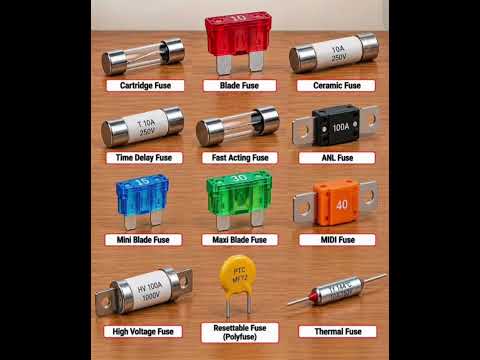
- Glass and Ceramic Cartridge Fuses: Commonly found in household appliances and power supplies. Glass allows easy visual inspection, while ceramic provides higher temperature resistance.
- Blade Fuses: The standard choice for automotive systems, color-coded by amperage rating for quick identification.
- High Rupturing Capacity (HRC) Fuses: Built for industrial environments, capable of safely handling high fault currents without causing external damage.
- Resettable Fuses (PTC): Polymeric devices that reset automatically after cooling down, making them ideal for modern smart devices and USB ports.
Identifying Fuses in Circuit Diagrams
When designing or troubleshooting a system, properly reading an electrical engineering schematic ensures that you select the right fuse for your specific load requirements. Circuit diagrams use standardized symbols—often depicted as a rectangle with a wire passing through it or a stylized squiggly line—to indicate fuse placement.
Before assembling or repairing any circuit board, always review the electrical engineering schematic to verify the required current rating, voltage limits, and response speed (fast-acting vs. time-delay). By selecting the correct fuse type, you guarantee maximum safety and long-term reliability for your electronic designs.


