Showing posts with label SolidWorks. Show all posts

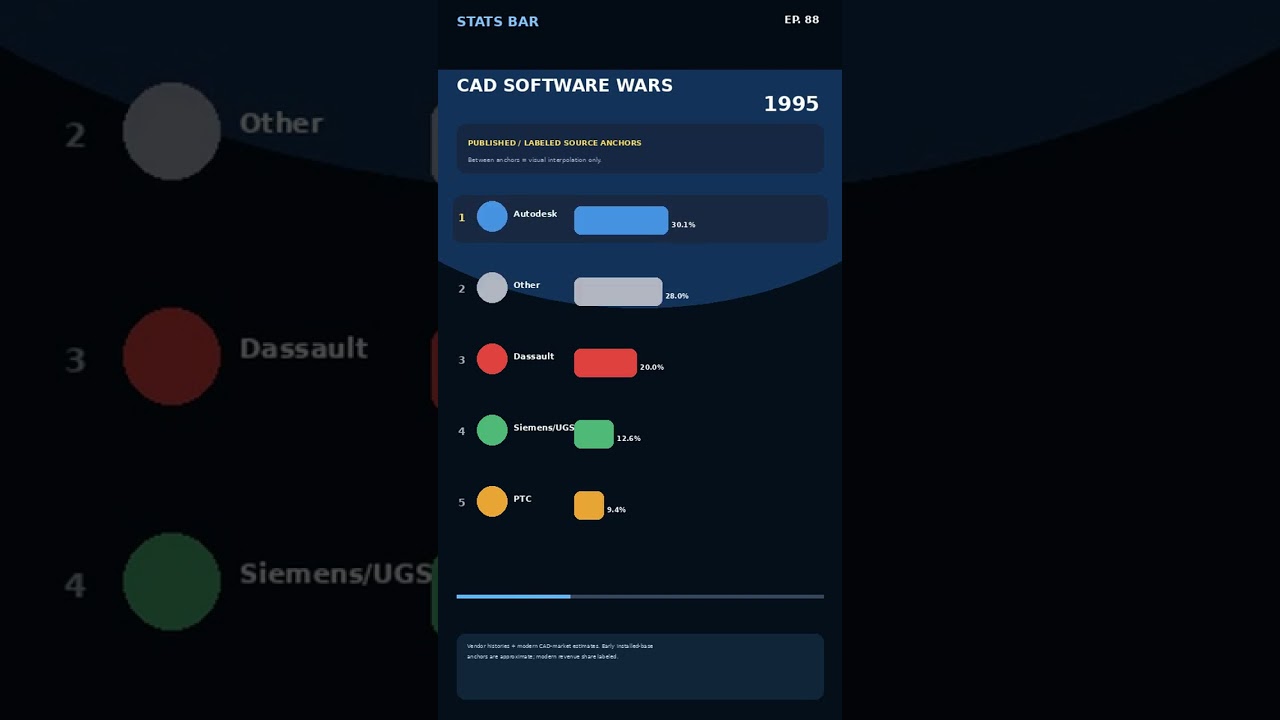
The CAD Software Wars (1982–2026): How AutoCAD, SolidWorks, CATIA, and Creo Shape Modern CAD Data

...
engineering information technology
The CAD Software Wars (1982–2026): How AutoCAD, SolidWorks, CATIA, and Creo Shape Modern CAD Data

The CAD Software Wars (1982–2026): How AutoCAD, SolidWorks, CATIA, and Creo Shape Modern CAD Data

This article provides an in-depth exploration of CAD data, covering foundational concepts, practical applications, and engineering insights.

Since the dawn of digital drafting in 1982, computer-aided design has undergone a massive transformation. What began as a simple replacement for physical drawing boards has evolved into a multi-billion-dollar industry driven by relentless innovation. The decades-long rivalry between industry giants—AutoCAD, SolidWorks, CATIA, and Creo—defines the history of modern engineering and dictates how engineering teams generate, store, and leverage CAD data today.

The Rise of Digital Drafting: AutoCAD and CATIA

In 1982, Autodesk introduced AutoCAD, revolutionizing architectural and engineering workflows by bringing 2D drafting to personal computers. Around the same time, Dassault Systèmes pushed aerospace and automotive engineering forward with CATIA, offering high-end 3D surface modeling capabilities. These early platforms laid the foundation for digital design, proving that computerized workflows could drastically reduce product development lifecycles and simplify complex geometry.

The Parametric Revolution: Creo and SolidWorks

The design landscape shifted dramatically with the introduction of parametric modeling. PTC’s Pro/ENGINEER (now known as Creo) introduced feature-based parametric modeling in the late 1980s, allowing engineers to modify dimensions and automatically update full product assemblies.

By 1995, SolidWorks entered the market with a user-friendly, Windows-native interface, making parametric 3D modeling accessible to mainstream product designers. This move sparked intense competition, forcing all major software vendors to continually refine their feature sets, rendering engines, and file interoperability systems.

The Future of Design: Managing Complex CAD Data

As we look toward 2026, the CAD software battleground has expanded beyond simple geometric creation. Today's engineering teams must handle massive volumes of complex CAD data across distributed global networks. Modern platforms now integrate cloud collaboration, real-time simulation, generative design, and Product Lifecycle Management (PLM) directly into the design ecosystem.

Ensuring seamless conversion, translation, and security of high-value CAD data across different software environments remains a top priority for organizations aiming to accelerate time-to-market and avoid costly production errors.

Conclusion

The evolution of AutoCAD, SolidWorks, CATIA, and Creo highlights an ongoing quest for efficiency, accuracy, and innovation in engineering. Whether you are designing consumer electronics, automotive components, or massive architectural structures, understanding this software history empowers teams to choose the best tools for their workflows and secure a competitive edge in the market.


🎬 Related Video Reference

How Simulation Software Improves Engineering Learning

...

In modern engineering education, simulation software has become an indispensable tool. By using simulation tools, students can visualize complex concepts, test theoretical models, and gain hands-on experience in a virtual environment. This enhances understanding, reduces errors, and fosters creativity in engineering problem-solving.

Simulation software such as ANSYS, SolidWorks, MATLAB, and Simulink allows learners to model real-world scenarios without the high cost or risk associated with physical experiments. Students can explore stress analysis, fluid dynamics, thermodynamics, and mechanical design in a controlled digital environment.

Moreover, simulation-based learning improves critical thinking, decision-making, and collaboration skills. Group projects using simulation tools encourage teamwork and communication, while instant feedback from software accelerates learning and mastery of complex engineering principles.

Incorporating simulation software into engineering curricula also aligns with industry standards. Future engineers familiar with these tools are better prepared for professional work, bridging the gap between academic knowledge and practical application.

In conclusion, simulation software revolutionizes engineering education by providing interactive, safe, and efficient learning experiences. It empowers students to experiment, innovate, and build confidence in their engineering abilities.

SolidWorks Motion Study: Design and simulate the operation of a simple belt conveyor with Belt/Chain Mate.

...


The video titled "Solidworks tutorial: Simple Belt Conveyor Design Assembly and Motion Study" from the Solidworks Fun channel teaches you how to design a simple belt conveyor using SolidWorks , focusing on the design process of parts, assembly, and motion simulation.

This video is 8 minutes and 17 seconds long and provides a good basis for conveyor system design:

Summary of main content of the video: Simple Belt Conveyor
This video covers all three main steps of mechanical design in SolidWorks:

1. Part Modeling
The instructor will begin by creating the necessary sub-components:

Structure/Frame: Creates the main structure of the conveyor belt. [00:10] which is usually made from box steel or aluminum profiles using Sketch and Extrude commands .

Pulleys/Rollers: Make the head and tail rollers [00:50] Used to drive and support the belt. Keyway or various mounting holes may be created.

Belt: Create a model of a conveyor belt [01:20] which may be created as a surface or solid model with some thickness.

2. Assembly
Mate Definition: Put all the parts together in an Assembly file [02:30] Using the command] Using Mate like Concentric for shafts and Coincident for plane placement.

3. Motion Study
Using the Belt/Chain Mate (Focus Point): The instructor will use the Belt/Chain Mate command [03:50] To precisely define the relationship so that the rotation of one roller/pulley causes the other rollers and the belt to move accordingly.

Motor Setting: Set Motor [04:20] to the main drive shaft by setting the rotation speed.

Contact Simulation: Set Contact [05:00] Between the product (such as a box) and the surface of the belt.

Animation Rendering: Video showing the complete working result [06:00] Where the belt moves and the boxes are transported smoothly along the belt.

This video is a complete tutorial on basic conveyor system design, focusing on using Belt/Chain Mate to simulate belt operation.


1. SolidWorks Motion Study: Design and simulate the operation of a simple belt conveyor with Belt/Chain Mate. Focuses on the types of belts (Belt Conveyor) and important commands (Belt/Chain Mate) used in motion simulation.
2. SolidWorks Tutorial: Creating a Simple Conveyor Belt with Complete Assembly and Motion Study Steps Emphasis on comprehensiveness of content from start to finish, from parts to simulations of actual work.
3. Design Guide: Create Pulleys and Belts in SolidWorks Assembly Using Mechanical Mates Focuses on the main components (Pulleys/Rollers) and assembly techniques used in constructing belt transmission systems.


Software/Program SolidWorks, Motion Study, SolidWorks Teaching, CAD Program SolidWorks, Motion Simulation, CAD, 3D Modeling
System/Mechanical Conveyor belt, Belt Conveyor, Conveyor system, Pulleys, Belt rollers Conveyor System, Belt Conveyor, Material Handling, Pulley, Roller
Features/Commands Belt/Chain Mate, Mechanical Mate, Assembly, Motor, Motion Simulation Belt/Chain Mate, Assembly, Motion Study, Motor, Contact
Design techniques Mechanical engineering, machine design, power transmission, conveyor systems Mechanical Engineering, Machine Design, Power Transmission, Kinematics
General search terms SolidWorks Assembly, Belt Making Tutorial, Belt Animation Conveyor Animation, SolidWorks Belt, Simple Conveyor Tutorial


SolidWorks Motion Study: Design and Simulation of the Plus Four Steam Engine

...


Video name "Solidworks Tutorial # 258 THE PLUS FOUR STEAM ENGINE by SW Easy Design" from the SOLIDWORKS EASY DESIGN channel is a video tutorial on designing and assembling a 3D model of The Plus Four Steam Engine using SolidWorks.

This video is 3 minutes and 7 seconds long and focuses on demonstrating the complete model and its working animation.

Summary of the main content of the video: The Plus Four Steam Engine
Although the video is short, it focuses on demonstrating SolidWorks' capabilities in creating and simulating complex piston mechanisms:

1. Part Modeling
Key Parts: The video shows a 3D model of a key part, such as:

Cylinder: The part where the piston moves.

Piston and Connecting Rod: The main mechanisms that receive steam pressure.

Crankshaft: The part that converts the linear motion of the piston into rotation.

Flywheel: The part that helps to make the rotation smooth.

2. Assembly and Mate display
Assembly: All models are assembled in an Assembly file [00:28] Using Mate to define the relationship so that the joints can move realistically (Kinematics).

3. Motion Simulation
Working Animation: Video showing the working results of Motion Study [00:58] Simulating the operation of a steam engine:

piston moves up and down in the cylinder.

Connecting rod , pushing crankshaft to rotate continuously.

Power steering rotates to demonstrate the smooth operation.

This video is a great example of using SolidWorks to design and demonstrate complex and historic mechanical mechanisms, such as steam engines.


1. SolidWorks Motion Study: Design and Simulation of the Plus Four Steam Engine Focus on the well-known pieces (Steam Engine) and the important functions used to demonstrate their operation (Motion Study).
2. SolidWorks Tutorial: Create Piston, Connecting Rod, and Crankshaft Mechanisms in a Steam Engine Emphasis on the main mechanical components of the engine, which is the study of the mechanism that converts linear motion into rotation.
3. SolidWorks Assembly: A Guide to the Complex Mechanisms of the Steam Engine (The Plus Four Steam Engine) emphasize the assembly process and define the relationship ( Mate ) so that all parts can work together.

Software/ProgramSolidWorks, SolidWorks tutorials, CAD programs, simulationSolidWorks, SolidWorks Tutorial, CAD, SimulationWorkpiece/MechanismSteam Engine, Steam Engine, Steam Mechanism, Piston Mechanism, The Plus FourSteam Engine, Piston, Connecting Rod, Crankshaft, FlywheelFeatures/CommandsMotion Study, Kinematics, Assembly, Motion Simulation, MateMotion Study, Kinematics, Dynamics, Assembly, MateDesign techniquesMechanical Engineering, Mechanism Design, Mechanics, Motion ConversionMechanical Engineering, Mechanism Design, Machine Design, Reciprocating MotionGeneral search termsSolidWorks Engine, Engine Animation, Steam Engine TutorialSteam Engine Animation, SolidWorks Model, Engine Kinematics

SolidWorks Motion Study: Simulating the Interaction of a Pick and Place Robot and a Conveyor

...


The video "Solidworks Motion study: Pick and Place Robot Moving Items on Roller Conveyors" from the Solidworks Fun channel is a tutorial video that simulates the movement of a Pick and Place Robot working with Roller Conveyors using SolidWorks Motion Study.

This video is short (1 minute 52 seconds) and focuses on an animation showing how the automation works together:

Summary of the main content of the video: Pick and Place robot on a conveyor belt
This video provides an overview of a complex automation system that integrates the movements of multiple mechanisms:

1. Operation of conveyor belt
Conveying: Roller Conveyor works [00:02] To transport objects (boxes/workpieces) into the robot's work area.

Workpiece Stopping: When the workpiece reaches the designated position, the stopper mechanism or roller will stop working. [00:08] To prepare for the robot to pick up

2. Operation of Pick and Place Robot
Picking up workpieces: Robot (may be Cartesian or Scara type) [00:10] will move down the axis (Z-axis) to pick up the workpiece.

Movement: The robot moves in the horizontal (XY-axis) and vertical (Z-axis) directions.00:15] To move the workpiece to a new location

Workpiece placement: Place the workpiece onto another roller conveyor belt or possibly another sorting area. [00:20]

3. System interaction (Motion Study)
Motor Settings: Motor settings are available [00:25] Make both the conveyor belt and the robot joints move in a specified time sequence.

Contact Simulation: Contact [ is used.00:30] To make picking up and placing workpieces realistic.

Animation Display: Video showing the results of a Motion Study where boxes are loaded, picked up by the robot, and placed away in a cycle. [00:40] It is a simulation of the complete operation cycle of an automated system.

This video is a great example of simulating a complex automation system in SolidWorks using Motion Study to examine the timing and kinematics of the entire system.


1. SolidWorks Motion Study: Simulating the Interaction of a Pick and Place Robot and a Conveyor Focus on the coordination between robots and conveyor belts, which is the heart of automation simulation.
2. SolidWorks Tutorial: Creating Pick and Place Robot Kinematics Emphasis on robot kinematics and animation creation steps in SolidWorks.
3. Design Guide: Factory Automation (Pick and Place) with Roller Conveyor in SolidWorks Focus on industrial applications to attract the target group of engineers and those interested in automation systems.


Software/Program SolidWorks, Motion Study, SolidWorks Teaching, CAD Program SolidWorks, Motion Simulation, CAD, Animation
System/Mechanism Robots, Pick and Place, Conveyor Belts, Pick and Place Systems, Automation Robot, Pick and Place, Conveyor System, Automation, Gripper
Features/Commands Kinematics, Dynamics, Joint Motion, Contact, Motor, Motion Simulation Kinematics, Dynamics, Motion Analysis, Contact, Motor, Assembly
Application Systems Engineering, Factory Automation, Machinery Design, Material Handling Systems Engineering, Factory Automation, Machine Design, Material Handling
General search terms SolidWorks Robot, Robot Animation, Mechanical Simulation Robot Animation, SolidWorks Mechanism, Pick and Place Tutorial

SolidWorks Tutorial: Design and Build a Car Jack with Expansion and Contraction Simulation with Screw Mate

...


The video titled "Solidworks Tutorial # 259 how to design a CAR JACK in solidworks Screen Size-16:10 Ratio" from the SOLIDWORKS EASY DESIGN channel is a video teaching how to design a 3D model of a Car Jack, which is usually a Scissor Jack type that uses a scissor mechanism, using the SolidWorks program.

This video is 18 minutes and 24 seconds long and demonstrates the construction of the various sub-assemblies and their assembly into a working mechanism.

Summary of the main content of the video: Car Jack design
This video focuses on the design of parts and the assembly of complex mechanisms (Kinematic Mechanism):

1. Part Modeling
The instructor will demonstrate the construction of a model of the parts that make up the jack:

Arms/Scissor Links: Create a model of the scissor cross-link [00:20] which uses Sketch and Extrude commands, including creating mounting holes.

Top & Bottom Bases: Create the weight-bearing parts and the parts that touch the ground.01:30]

Lead Screw: Create a model of the threaded shaft [02:40] which is the key to converting rotation into vertical movement.

Drive nut (Nut/Slider): Creates a part that runs along a thread [03:50] and connect with cross legs

2. Assembly
Mechanism Assembly: Assemble all the parts in the Assembly file [05:00]

Using Mechanical Mates (Focus): This is the most important part. The instructor will use the Mate commands to create relationships that are similar to real work:

Concentric Mate: For holes and shafts

Coincident Mate: For surfaces that touch each other

Screw Mate: Used for threaded shafts [06:40] by specifying the pitch of the thread so that one revolution of the screw results in the correct longitudinal movement.

3. Motion Simulation
Functional Testing: Once all Mates are defined [09:00] The instructor will test by rotating a threaded screw (or using the Motor in the Motion Study) to demonstrate that the scissor mechanism will open and close correctly, allowing the jack to raise and lower the vehicle.

This video is therefore a good tutorial for learning how to design and model mechanisms that convert angular motion into linear motion in SolidWorks.


1. SolidWorks Tutorial: Design and Build a Car Jack with Expansion and Contraction Simulation with Screw Mate Focus on the workpiece (Car Jack) and key commands (Screw Mate) used to simulate the actual working mechanism.
2. SolidWorks Assembly: Guide to Creating Angular to Linear Motion Mechanisms Emphasis on the mechanical principle used by the jack, which is to convert the rotation of the screw into the up and down movement of the jack.
3. SolidWorks Part Modeling: Create a Scissor Jack part and define the Mate to make the mechanism work. Emphasis on the construction steps, both sub-parts and assembly, so that users who are practicing can follow along.


Software/Program SolidWorks, SolidWorks teaching, CAD programs, modeling SolidWorks, SolidWorks Tutorial, CAD, 3D Modeling
Workpiece/Mechanism Car Jack, Car Jack, Scissor Jack, Scissor Jack, Car Lifting Mechanism Car Jack, Scissor Mechanism, Lifting Jack, Screw Mechanism
Features/Commands Screw Mate, Mechanical Mate, Assembly, Motion Simulation Screw Mate, Assembly, Kinematics, Motion Simulation, Mate
Design techniques Mechanical Engineering, Mechanism Design, Motion Conversion, Component Design Mechanical Engineering, Mechanism Design, Linear Motion, Part Modeling
General search terms SolidWorks Assembly, Jack Making Tutorial, SolidWorks Exercises SolidWorks Exercise, Design Tutorial, Lead Screw


SolidWorks Motion Study Advanced: Simulate Proximity Sensors and Event-based Recognition Systems

...


The video titled "Solidworks Proximity Sensor, Event based Motion Study for Product Sorting Conveyor" from the Solidworks Fun channel is a video tutorial on using advanced functions of SolidWorks Motion Study , specifically Event-based Motion Study and Proximity Sensor simulation , to create a conveyor system for automatic product sorting (Sorting Conveyor) that responds to real conditions.

The video is 13 minutes and 18 seconds long and is a highly complex simulation:

Summary of the main content of the video: Event-Based Sorting System Simulation
This video focuses on making the pusher mechanism work automatically when an item is detected, rather than on a time-based basis.

1. Proximity Sensor Simulation
Creating a Sensor: The instructor will show you how to use the Sensor tool in SolidWorks to model the operation of a Proximity Sensor .00:20]

Conditional Setting: The sensor is set to detect when a workpiece (box) enters a specified range, simulating the operation of a sensor in a real factory.

2. Setting up Event-based Motion Study
Motion Study Format Change: The instructor changed from Time-based Motion Study to Event-based Motion Study [03:12]

Creating an Event: This is the key step [03:27] by setting the Event to occur when the previously created Sensor detects the product.

Action Definition: When an Event occurs (sensor detected), the defined Action is:

Motor/Actuator Works: The pusher mechanism is activated (extended) immediately to push the product off the belt.

3. Automatic simulation
Contact and Motor Simulation: The contact between the box and the belt is set and the Motor is set to make the conveyor belt rotate. [11:42]

Display: When the simulation is run, the sorting mechanism will automatically work when the boxes pass through the simulated sensors, making the sorting system more accurate and realistic compared to running on pre-set times.

This video is an excellent tutorial on creating complex and interactive dynamics simulation models in SolidWorks, an essential skill for automation engineers.


1. SolidWorks Motion Study Advanced: Simulate Proximity Sensors and Event-based Recognition Systems Focus on advanced techniques used in simulation (Event-based and Sensor) which are the core of the video.
2. SolidWorks Tutorial: Create an automated sorting system that responds instantly to object detection Emphasis on realistic system functionality , which is sensor-driven, not time-driven.
3. Engineering Handbook: Application of Sensor and Event-based Motion in Conveyor Design Focus on engineering applications to attract the target group of system and automation engineers.


Software/Techniques SolidWorks, Motion Study, Event-based, Sensor, Advanced Simulation SolidWorks, Advanced Motion, Event-based Simulation, Proximity Sensor
System/Mechanism Sorting system, Sorting Conveyor, Automatic mechanism, Detection sensor Sorting Mechanism, Automation, Conveyor System, Sensor Detection
Features/Commands Proximity Sensor, Event-based Motion Study, Actuator, Event Response Sensor Setup, Event Action, Conditional Motion, Dynamics Simulation
Application Systems engineering, factory automation, sensor-based machine design Systems Engineering, Factory Automation, Sensor-Based Design
General search terms Teach SolidWorks Motion, Sensor Simulation, Advanced SolidWorks SolidWorks Sensor, Motion Simulation Tutorial

SolidWorks Add-In: Solid Plant 3DS for factory and structural automation design

...


The video titled "Solidworks Tutorial # 260 Automatic Design in Solidwork Using Solid Plant 3DS Add-Ins" from the SOLIDWORKS EASY DESIGN channel is a video tutorial on using an external Add-In called Solid Plant 3DS to help automate the design of plant and system work in SolidWorks.

Summary of the main content of the video: Automated design with Solid Plant 3DS
This video highlights the use of automated tools to create large-scale factory parts and structures without the need for manual repetitive modeling:

1. Activating the Add-In
Accessing Solid Plant 3DS: The instructor demonstrates how to activate Solid Plant 3DS [00:20] which is an Add-In specifically designed for plant engineering and structural design (Plant Design).

2. Creation of an automated factory structure (Automated Structure)
Creating Grids and Layouts: Instructors may use the tools in Solid Plant 3DS [00:30] To quickly create a 3D layout or grid structure, which is the basis for the layout of equipment and plant structure.

Steel Structures Creation: The Add-In's standard parts library is used.01:00] to automatically generate beams, columns, and steel frames (e.g. I-beam, C-channel) along a defined grid, saving you time from manually modeling Weldments.

Entering details: Specifying the standard connection details (Connections) or supports (Supports) [01:40]

3. Piping & Routing System Design
Using the Equipment Warehouse: Solid Plant 3DS has a large parts warehouse for plant equipment such as pumps, valves, and pipes.02:10]

Automated Piping Routing: The instructor demonstrates the use of the Add-In's Routing tools [02:40] To define the route of pipe laying from one point to another, the program will create a pipe model and automatically insert elbows, flanges and valves.

This video is therefore useful for those working in plant, structural, or piping engineering who need to use special tools to increase speed and accuracy in large-scale design in SolidWorks.


1. SolidWorks Add-In: Solid Plant 3DS for factory and structural automation design Focus on Add-In names and key features for large-scale factory structure design.
2. SolidWorks Tutorial: Quickly Create Weldments and Piping with Solid Plant 3DS It emphasizes the type of workpieces that are automatically generated (steel frames and pipes), which is the highlight of this Add-In.
3. Design Guide: Piping Routing in SolidWorks using Solid Plant 3DS Focus on specialized functions such as route planning and automatic generation of pipeline system models.


Software/Tools SolidWorks, Add-Ins, Solid Plant 3DS, Automated Design SolidWorks, CAD Add-In, Automatic Design, Solid Plant 3DS
Engineering work Plant Engineering, Structure, Piping, Plant Design, Steel Structure Plant Engineering, Steel Structure, Piping Design, Weldments
Features/Functions Routing, Automated Pipe Laying, Grid System, Library, Component Placement Piping Routing, Automatic Routing, Grid Layout, Design Library
General search terms Teaching SolidWorks, Factory Construction, Piping Design, Advanced SolidWorks SolidWorks Advanced, Plant Modeling, Piping Tutorial

Design Guide: Bottle/Can Inverting Mechanism (Inverter) in a Packaging Plant with SolidWorks

...


The video titled "Solidworks tutorial: Bottle/Can Twister Conveyor Designing and Motion Study" from the Solidworks Fun channel teaches how to design and simulate a Twister/Inverter Conveyor using SolidWorks.

A Twister Conveyor system is a mechanism used in packaging plants to turn bottles or cans upside down (i.e. from upright to inverted) for the purpose of washing, filling, or labeling.

Summary of the main content of the video: Twister Conveyor
This video is 18 minutes and 54 seconds long and focuses on creating the complex shape of the Twist Guide and simulating its movement:

1. Twister Guide Modeling
Creating a 3D Helix/Spiral: The instructor uses the Helix and Spiral commands to create a 3D curve that has a twisted appearance. [00:20] This line will determine the rotation path of the bottle.

Creating a Lofted/Sweep Surface: Use the profile shape of the bottle/can and use the Lofted Boss/Base or Swept Boss/Base commands .01:40] Using the spiral line as a guide, create a guide piece that is a twisted surface.

2. Assembly
Create a bottle/can model: Create a model of the product to be transported. [04:10]

Assembly: Assemble the twist guide into the conveyor belt structure. [05:30] and place the bottle/can model in the Assembly.

3. Motion Study
Motor and Contact Setting: Set the Motor to the conveyor to push the bottles into the system. [07:00] and set Contact [08:40] Between the bottle/can model and the twist guide surface

Torsion Simulation: When running Motion Study [10:00] The twisting mechanism works by the twisting surfaces exerting a force that causes the bottle to rotate and invert while realistically moving forward.

This video demonstrates the design of a mechanism that involves a twisted surface and the simulation of the interaction between the curved surface and the workpiece in a Motion Study.


1. SolidWorks Motion Study: Design a Twister Conveyor to Realistically Rotate Bottles/Cans 180° Emphasis on the working mechanism (Twister/Inverter) and simulation function (Motion Study) used in packaging system design.
2. SolidWorks Tutorial: Create a Twisted Surface with the Loft Command for Twister Guides Emphasis on complex modeling techniques , especially creating twisted guide surfaces using the Loft/Sweep command.
3. Design Guide: Bottle/Can Inverting Mechanism (Inverter) in a Packaging Plant with SolidWorks Focus on industrial applications to attract target groups working in packaging machinery.


Software/Program SolidWorks, SolidWorks tutorials, CAD programs, simulation SolidWorks, SolidWorks Tutorial, CAD, Simulation
System/Mechanical Conveyor belt, Twister Conveyor, Bottle Rotator, Inverter Conveyor, Packaging System Bottle Twister, Can Inverter, Packaging System, Conveyor, Twisted Guide
Features/Techniques Motion Study, Motion Simulation, Loft, Sweep, Twisted Surface, Helix and Spiral Motion Study, Dynamics, Lofted Boss, Swept Surface, Twisted Surface, Contact
Application Packaging factory, machinery design, systems engineering, mechanism construction Packaging Machinery, Machine Design, Systems Engineering, Automation
General search terms SolidWorks Assembly, Threading Tutorial, Machine Design SolidWorks Animation, Helix Design, Conveyor Mechanism

SolidWorks: How to enable the Routing Design Library and Forming Tool for pipe and sheet metal work

...


The video titled "Solidworks Tutorial # 263 How to Enable the Routing Design Library & Forming Tool in Side Manager" from the SOLIDWORKS EASY DESIGN channel teaches you how to set up and enable specific features of SolidWorks that are essential for advanced piping/wiring and sheet metal design.

This video is short (3 minutes 27 seconds) and focuses on the management steps within the program:

Summary of the main content of the video: Setting up a Library in SolidWorks
This video demonstrates how to access and configure the tools so that users can use standard tools and parts libraries (Design Library) for specific tasks:

1. Enabling Add-ins (for Routing)
Routing Design Library: The instructor will show you how to enable the add-in called SolidWorks Routing (for ductwork, flexible pipe, HVAC ductwork, and electrical wiring).00:28] This activation gives users access to standard commands and components for designing such systems.

2. Design Library location determination
Enter System Options: The teacher will enter the Options menu or System Options [00:58] To specify the folder location for the Design Library.

Specifying the Path: The instructor will point to the File Locations tab and specify the Path (folder address) where the Routing Design Library and Forming Tool Library files are stored. [01:58]

3. Activating the Forming Tool (for Sheet Metal work)
Forming Tool: The instructor will focus on activating the Forming Tool library [02:28] which is a special tool for Sheet Metal work.

Purpose: Forming Tools are used to create special features on sheet metal, such as creating louvers, domes, or drilling holes of complex shapes, while still allowing the workpiece to form a flat pattern.

This video is an important setup guide for SolidWorks users who want to use the Routing feature for pipe/wiring work or use the Forming Tool to design sheet metal parts with complex details.


1. SolidWorks: How to enable the Routing Design Library and Forming Tool for pipe and sheet metal work It focuses on two main functions that are enabled (Routing and Forming Tool) to meet the needs of intermediate/advanced users.
2. SolidWorks Tutorial: Setting Up the Correct Design Library and File Locations (Very Important!) Emphasis on setup steps and importance of folder management for design libraries to use standard tools.
3. SolidWorks Add-ins: Guide to Activating the Forming Tool to Create Complex Shapes in Sheet Metal Focus on Forming Tools , which are specialized tools and are in demand by those who work in sheet metal design.


Software/Program SolidWorks, SolidWorks tutorials, SolidWorks settings, CAD programs SolidWorks, SolidWorks Tutorial, CAD Software, Settings
Key features Routing Design Library, Forming Tool, Design Library, Add-ins Routing, Forming Tool, Sheet Metal, Pipe Routing
Application Sheet metal work, piping work, system work, parts inventory management, machinery design Sheet Metal Design, Piping, Tube Routing, Library Management
Commands/Menu System Options, File Locations, Activation, Settings SolidWorks Options, File Path, Enable Add-ins
General search terms Teaching how to open Forming Tool, SolidWorks Sheet Metal, and set up Library SolidWorks Library, Forming Tool Setup

SolidWorks Motion Study: Design and simulation of a sorting mechanism on a conveyor belt.

...


The video titled "Product Sorting Roller Conveyor Subassembly Motion Study in Solidworks || Series- 4" from the Solidworks Fun channel is a video tutorial on designing and simulating the operation of a Product Sorting Roller Conveyor subassembly using SolidWorks.

This video is part 4 (Series-4) in the Conveyor System Design Tutorial series, which focuses on simulating the sorting mechanism of products from the main conveyor:

Summary of the main content of the video (Series-4)
This video focuses on adding a Sorting Mechanism and setting up a Motion Study to simulate its operation:

1. Construction and assembly of sorting mechanisms
Pusher/Stopper Design: The instructor will create a part that acts as a stopper or pusher for the product off the conveyor belt.00:20]

Adding an Actuator: Create a drive mechanism for the pusher, possibly using a pneumatic cylinder or solenoid.01:30] or simulate its operation

Mechanism Assembly: These parts are assembled into the conveyor structure using Mate to determine the linear movement of the pusher. [02:40]

2. Setting up Motion Study for Sorting (Sorting Motion Study)
Motor and Contact Setting: As in the previous series, the Motor is set to rotate the roller and the Contact between the product and the roller is set. [04:00]

Actuator Simulation: This is the most important step [05:30] The instructor will use Motion Actuator commands (such as Linear Motor) or define more complex Force/Contact to make the pusher move in a specified time (Timed Motion).

Sorting simulation: When the goods (boxes) are transported to the sorting point [06:40] The actuator will operate, pushing the specified box out of the main conveyor belt to another path.

3. Animation display
The video shows a complete animation showing the product moving along the conveyor belt and being pushed out by the sorting mechanism at precisely the set time. [08:00]

This video demonstrates the design of an automated system with complex decision (sorting) and movement, using SolidWorks' Motion Study tool to examine and simulate the operation of the sorting mechanism.


1. SolidWorks Motion Study: Design and simulation of a sorting mechanism on a conveyor belt. The main function is to simulate the movement of the sorting mechanism added to the system.
2. SolidWorks Assembly: Creating Subassemblies for an Automatic Product Sorting System Focus on the type of system designed (automatic sorting system) and assembly techniques (subassembly).
3. SolidWorks Tutorial: How to Make a Pusher Sort Boxes from a Conveyor Belt with Timed Motion Emphasis on the working steps of the sorting mechanism and the use of timed motion in Motion Study.


Software/Program SolidWorks, SolidWorks tutorials, CAD programs, simulation SolidWorks, SolidWorks Tutorial, CAD, Simulation
System/Mechanism Sorting System, Sorting Conveyor, Sorting Mechanism, Pusher Mechanism, Conveyor Belt Product Sorting, Sorting System, Pusher, Actuator, Roller Conveyor
Features/Functions Motion Study, Motion Simulation, Assembly, Timed Motion, Contact Motion Study, Dynamics, Timed Motion, Subassembly, Actuator
Application Automation, Material Handling, Manufacturing Engineering, Machinery Design Automation, Material Handling, Manufacturing Engineering, Machine Design
General search terms SolidWorks Assembly, teaching sorting systems, designing factory mechanisms SolidWorks Assembly, Sorting Animation, Factory Automation