Showing posts with label Industrial Electronics. Show all posts

How To Read Colour Codes in Resistor

online engineering degree/engineering degree online/online engineering courses/engineering technology online/engineering courses online/engineering technician degree online/online engineering technology/electronic engineering online
A resistor is a passive two-terminal electrical component that implements electrical resistance as a circuit element. It’s ability to restrict electric current is various depend on the value of the resistor itself. In this article, we will learn how to read the colour codes in resistor to know it’s value. Enjoy!

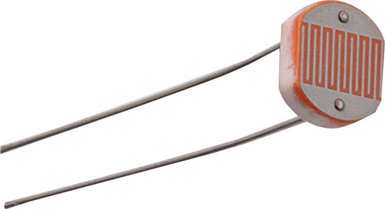
The common shape of resistor is like the picture below :


There are 3 kind of resistor that use the colour codes, they are :
  1. Resistor with 4 colour band with 1 colour band as tolerance
  2. Resistor with 5 colour band with 1 colour band as tolerance
  3. Resistor with 5 colour band with 1 colour band as tolerance and 1 colour band as reliability


To read the resistor colour codes, we can simply look at the following table, and it can easily memorized too!!


To help you understand the table, we can try to read a resistor like the picture shown below :


To read the resistor code, follow these simple easy steps :
  1. Place the resistor in front of you with the tolerance band (gold or silver) on your right side. Sometimes there will be no tolerance band, simlply find the side that has a band closest to a lead and make that the first band.  
  2. The first colour on your left is the first digit  ( Brown = 1)
  3.  The second colour is the second digit  ( Brown = 1 )
  4. The third number is the third digit ( Black = 0 )
  5. The fourth colour indicates the numberof zero to add ( Red = 2 ) (Gold, multiply by 0,1)(silver multiply by 0,01)
  6. The fifth colour is the tolerance (Gold = ± 5%)
Therefore: a Brown, Brown, Black, Red, Gold resistor would be a 1 1 0 00 = 11000 ohms with a tolerance 5%
This can be written as 11,0 K.
Here are some othe exmple to help you understand more about the colour codes in resistor

Remember the colour codes with this sentences: Big Brown Rabbits Often
Yield Great Big Vocal Groans When Gingerly Slapped

(Black Brown Red Orangs Yellow Green Blue Violet Grey White Gold Silver)

Hope you understand more about colour codes in resistor, Good Luck Everyone :)
(DEYA IKA WARDANI 112110038)

Types of Switches that Mostly Used in Industries

online engineering degree/engineering degree online/online engineering courses/engineering technology online/engineering courses online/engineering technician degree online/online engineering technology/electronic engineering online
Switch is a device that can break a circuit and also connect them again to set some kind of electrical things. This device can be referred as one of the main device in a circuit. There’s a lot of switches that usually used in industrial aspects:
  • Toggle Switch

This kind of switch is the most common switch that we used daily. the mechanism is as simple as breaking and connecting the circuit current.

  • Slide Switch

this kind of switch is usually used in small scale circuit. the mechanism is quite same with toggle switch but with "slide" operations. this slide is also can be used as selector switch.
  • Push Button Switch
this also types of switches that really familiar with our daily lives. this is a kind of mechanical switches that manually break or connect the circuit by using spring mechanism that applied to the button.

  • Rotary Switch
This switch is usually used for switching some condition in electrical circuit. This kind of circuit is operated by twisting the head until the indicator is indicating certain condition.
this applied to in switching multiple conditions in electrical circuits.

  • Temperature Switch

this kind of switch is using temperature as the parameter to operate. certain temperature level is set to operate this kind of switch. it can be useful for setting some safety factor in industries.

  • Liquid Level Switch

this switches using floating object principle to operate, it will give an action when the floating object is reacing certain level. it can also called as liquid level sensor. it can be applied for valve control in a water reservoir.

  • Pressure Switches 

          Pressure switches is a switch that using a certain pressure level as the input. this kind of switch is usually used in automobiles industries. it's also can be used for controlling safety factor in a production floor. this kind of switch divided into Pneumatic switches and Hydraulic Switches.


However, switch is an important device that used in electrical thing, the application of this device is highly various depends on what's needed.


Author : Randy Pradana - 112110094 - TI 35 INT - Telkom Institute of Technology


Induction Heating

online engineering degree/engineering degree online/online engineering courses/engineering technology online/engineering courses online/engineering technician degree online/online engineering technology/electronic engineering online

Induction heating is unique. As compered the most conventional heating processes use for pre-heating and stress for leaving. It is non-contact method of quickly heating metal by inducting current in the part. Therefore it does not rely on heating element to touch the part to conduct heat or flame to the part.

Induction heating conventional uses are many, for example : brazing, melting, forging, super heating, etc. now induction heating being successful use in industrial and construction application involving welding, such as pre-heating before welding and stress for leaving after welding.


So, what happened in induction heating? When the electrical current flows through conductor, it produces a magnetic field around the conductor.

By alternating the current, the magnetic field is reversed. Placing conducting material like metal, in the alternating magnetic field, causes the material heat up. Localize electrical current called eddy currents are created within the metal. The metal has a certain electrical resistance. The circulating eddy currents flow against the metal resistance, causing it heat up.

Another contributing factor to heating is hysteresis. This is crisis due to the material resistance to the changing magnetic field. Eddy current heating provides significantly more heating than hysteresis.


 Induction Heating for Pre-heating or Stress for leaving

Induction heating uses conductive cable which can be rope around or placed on a metal part to be heated. Alternating current passes through the cable, creating a magnetic field in the part. They reversing magnetic field create eddy currents and hysteresis and then create heat.
The part becomes the heating elements and the highest temperature is generated and control in the part rather than heating device. This makes induction heating really efficient.

Some benefits of induction heating:
  • Temperature uniformity
  •  Automatic temperature control
  • Reduce cycle time (quick time to temperature)
  •  Lower consumable cost( not using fuel gas )
  • Simple and using friendly
  • Safety
  • Flexibility (pre-heat, stress for leaving, etc)
  • Power efficiency
  • Reliability (no burned connectors or wires or open heating pads)

Dian Ayu Aprianti (112110091)


LADSIM - Ladder Logic Simulator

online engineering degree/engineering degree online/online engineering courses/engineering technology online/engineering courses online/engineering technician degree online/online engineering technology/electronic engineering online

LADSIM is a fully functional ladder logic design and PLC simulation software program that incorporates the functions used in PLC ladder programming. LADSIM uses the PC as a virtual PLC.

   Figure 1. LADSIM Interface

There are three main screen of LADSIM:
1.      The Ladder Logic Diagram Window
      This is where the ladder code is displayed. Each time you add or edit a rung, the result will be shown here. 


       Rung is serves as conditioning for command input and output logic.
2.      The Controls box.
      This contains the ladder symbols that are used to create the ladder diagram. See below for further details. 


3.      The toolbar
      This includes the standard buttons of LADSIM and allows you to start a new diagram, open an existing file, print, save and comment your ladder diagram.


You aso can apply your ladder code to run simulations in LADSIM. These simulations are:   
1.       Traffic Light
 
      Code must be written to control the sequence of operation of the lights. A typical sequence could be : RED 'ON' immediately After 2 seconds YELLOW 'ON' After 3 seconds GREEN 'ON' only After 5 seconds YELLOW 'ON' only After 1 second Restart Sequence. The task would be to code this sequence in ladder logic and operate the lights accordingly.

2.       The Annunciator
       In industry, plant conditions need to be monitored and, if there are problems, a way of indicating these problems. An indicator system of this type is called an annunciator. A typical alarm system uses the following sequence to indicate a plant alarm condition to an operator. System healthy - no indication. System in alarm - a flashing light and audible alarm.
The annunciator in LADSIM must be programmed to allow the correct operation. 

3.       The Car Park
      The diagram shows the layout of a simple car park. It has an entry barrier and an exit barrier. The car park itself has six spaces and a series of displays to indicate whether it is full, has spaces or is empty, with a numerical indicator to determine the exact amount.
Ladder code needs to be written that will allow cars into the car park when it is empty or has spaces and to exit the car park through the correct barrier. Ladder code must also be written to control the display boxes in the centre of the screen.

4.       The Lift (Elevator)
      A program is required that will drive the lift from one floor to the other on a signal from the call button. Safety is essential and we must be careful not to have anything obstructing the operation of the doors.
 

5.       The Drinks Machine
       When a coin is placed into the slot, the user should be able to select his or her favourite drink or reject the coin. It is important to ensure that the coin cannot be rejected once a drink has been selected or that selecting a drink disables all of the other drink buttons. 

6.       The Packing Line
      The packing line carries boxes of different sizes which need to be separated into their relevant sizes.
Which direction the boxes go is decided by using the input sensors IP0 and IP1. If a box is short, only one of the inputs is energised at any one time. If it is a long box, then both inputs will be energised. These results can then be used to activate the correct solenoid and the direction of rotation of the circular plate.

 7.       The Bottling Plant
       The graphic is an overview of a simplified bottling plant with a filling station and packing area. Bottles are fed along the first conveyor, conveyor 1, into the filling station. The bottles must be stopped and filled with milk and then have a cap placed on them. Once accomplished, they go onto conveyor 2 where the cap is screwed on tight. They are finally stacked in the stacker area where they are pushed onto conveyor 3.